What are the differences between the different types of compressors? OPTO, FET, VCA, VARI-MU?
Compression can be accomplished in different ways, hence the different type of compressors. Every different type of compressor sounds different, e.g. one may sound better on certain things than the other. Lets find out how these different types of compressors work, and in which situation we can best use a particular type of compression!
Tip: To follow along with this article it is convenient that you understand how compression works in general. If you’re not sure what terms like; ratio, attack, release, or threshold mean, or just want a quick read up. Then this article I wrote about compression in general might be helpful! While you’re at it, this post could also be interesting where I explain the different types of compression (I’m currently still writing these articles)
Summary
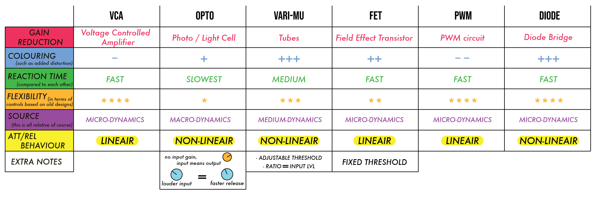
The following table is basically a summary of this whole article. If this doesn’t make sense to you right now, it will once you’re done reading this article. The table can be used as reference whenever you quickly need to access all the information described in this article. While I would suggest you to experiment with different compressors on different sources, this table can be used to help you figure out what type of compressor would work best. Remember that this is all relative, and you should therefore always trust your ears. When you’re deciding what type of compressor or what combination of compressors you will use, you could ask yourself one of the following questions:
- (1.) How dynamic is the source I want to compress?
- (2.) Do I want the compressor to only reduce the gain, or do I also want it to colour the source?
- (3.) How much control do I want?
This is a list of different types of compressors that are covered in this article:
VCA
OPTO
VARI-MU (TUBE)
FET
PWM
Diode Bridge Compressor
VCA (Voltage Controlled Amplifier)
While the A in VCA stands for Amplifier it’s actually more often an attenuator, meaning that it turns the signal down when it’s fed a certain control voltage. In simple terms that’s how the gain reduction takes place in a VCA compressor;
You dial in a control signal using the different front panel controls:
- With the treshold knob you tell the compressor when to start turning the signal down.
- With the attack knob you tell it how fast to do it
- With the ratio knob you decide how much to do it
- And with the release knob you decide how long it should take for the signal volume to return to normal.

What VCA compressors are known for
VCA compressors are sensitive to micro-dynamics and transients. Most of them have a hard knee, but some compressors allow you to adjust the knee to a more soft-knee (just like the api 2500 in the picture above for example). A VCA compressor is known for it’s transparency and offers the highest possible amounts of gain reduction compared to the other types of compressors. Also the design of a VCA compressor allows for a lot of control.
What are they used on?
Because VCA compressors are extremely fast they work really well on instruments that have big differences in transients such as percussion. In other words, it can be good on things with drastic chances. However, VCA compressors are also widely used by both mixing and mastering engineers as mixbus compressor. This is because the design allows for a lot of control, a wide range of response times, and can be made to react very quickly if desired. This gives you all the power you need to create cohesion and punch in your mixes, regardless of the type of song, the tempo, or how loud specific instruments may be. Besides that, lets not forget that the VCA compressor is quite a transparent compressor. If you’re thinking of investing your money into 1 compressor for your mix bus, then a stereo VCA compressor is a smart choice since it covers a lot of different ground.
COMPRESSORS THAT USE A VCA FOR GR:
SSL G-series Stereo Compressor
API 2500
Neve 30609
Focusrite RED 3
Vertigo VSC-2
Shadow Hills Dual Vandergraph
Shadow Hills Mastering Compressor (Opto Stereo + VCA Stereo)
Dramastic Obsidian Stereo Compressor
DBX 160
Alan Smart C1
Kush Audio Tweaker
Foote P3EX
P3
Smart Research C2
Smart Research C1LA
Serpent Audio SB4001
Dangerous Compressor
Overstayer Stereo Voltage Control
OPTO
An OPTO compressor uses the incoming audio signal to feed a lighting element (such as a LED (new design), lightbulb (older design)) and the LED shines upon a light-sensitive resistor. The resistance of this light-sensitive element informs the compression circuit how much and how quickly the audio signal should be attenuated. In other words; the gain reduction is controlled by a photo or light cell, and that’s exactly what makes this design so unique. The way the photocell reacts to the light source ensures that there is some inherent delay in the response time to trigger the attack and the release of the compressor. Many people describe this response time as smooth and musical; the attack is rather fast and the initial release as well, but then it tapers off in its release rate as it decays.
Why every OPTO compressor can sound different
The sound of an OPTO compressor depends on what types of materials were used in its construction. For example: different type of light sources will illuminate at different speeds. But not only changing the type of light will affect the sound, also a resistor can react differently depending on the material from which it was made. One of the most famous OPTO compressors is the LA-2A, which is a tube-based design that uses the military designed T4 photoresistor. The T4 is a cell that has nearly infinite resistance as long as it is dark. But when light hits the surface of the T4 it causes a drop in resistance. Therefore they could use the cell to control the gain reduction. The T4 cell in a LA-2a has (according to the original specs) an attack of 10ms and a gradually sloping release that can last up to five seconds depending on the program material.
What OPTO compressors are known for
One thing all OPTO compressors have in common (no matter the materials that were used) is that they are the slowest type of compression. At least that goes for OPTO compressors that use older designs. Nowadays with new modern designs, it is actually possible to create an OPTO compressor that reacts as fast as a VCA compressor. However, an OPTO compressor is known for being very slow. Besides being slow, the older ‘classic’ designs have an attack and release that are almost always not linear. The harder your hit an OPTO compressor the quicker its initial release time can be. However, the slope from compressed signal to uncompressed signal will not fall in linear fashion. This means that if you set the gain-reduction to 10 dB, the first 5 decibels might release much more quickly than the following 5.
Note: Some inexpensive compressors on the market claim to have an optical emulation mode available. In many instances this is just a slower attack and/or release time and really doesn’t properly emulate the behaviour of a real OPTO compressor. There are some digital emulations that come pretty close though.
What are they used on?
An OPTO compressor is good at taking care of macro-dynamics. If you have a song that starts quiet and ends loud a VCA compressor will do nothing at the beginning and will smash the signal at the end (depending on your settings of course). An OPTO compressor will smooth things out and will have a more consistent level throughout the song. When you want to tighten up your mix a little bit without losing transients, use an OPTO compressor on your mixbus, but be careful of pumping which will boost the low end content. To prevent this from happening you can use a high-pass filter in side-chain mode. It also works really well on bass, guitars, and vocals. But then again it depends on the performance, if the performance has lots of transients you might be better of using a different type of compression or perhaps a combination of two.
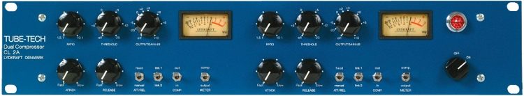
Here are some audio examples that were compressed using the CL2A by TUBE-TECH (see image above). If you’d like to listen to more examples then click here.
Bass Guitar - BYPASS
Bass Guitar - CL2A ON
Guitar - BYPASS
Guitar - CL2A ON
How to use an OPTO compressor?
Unlike a FET compressor the input-level of an OPTO compressor usually cannot be changed inside of the device. So if you’re driving the compressor without any compression happening, you’ll have to bring down the output level of the preamp, unless that’s the sound you’re going for. Most OPTO compressors have two knobs. One for the gain and one for threshold. The threshold a.k.a. the peak reduction knob determines at what level the compressor will begin to engage. So if you want lots of compression you’ll set a lower threshold (which is a higher peak reduction), and if you want less compression you set a higher threshold (which is a lower peak reduction). The input-gain knob is placed after the compression and IS NOT the input gain to the compressor. It actually is the output gain to your DAW or tape machine. It is called the ‘input-gain’ because it determines how loud the signal will be send into your DAW or tape machine.
Tip: You can use an OPTO compressor as a signal booster. If the source was tracked at a low level, you can run it through an optical compressor and keep the threshold all the way up so that there won’t be any compression at all. Now use the gain knob to add more level to the signal. Despite not using any compression the OPTO compressor may add a little colour to your source as well.
COMPRESSORS THAT USE PHOTO/LIGHT CELL FOR GR:
LA-2A
LA-3A
LA-4A
TubeTech CL1B
Manley ELOP
SHMC
Aurora Audio GTC2
Acme Audio Opticom XLA-3 MKII
Retro Instruments Sta-Level
Buzz Audio SOC 1.1 / 2.0
Inward Connections VAC RAC
The Brute 2
VARIABLE MU (TUBE COMPRESSOR)
It’s the earliest compressor design you can find. The amount of compression it uses is far from linear. The actual ratio increases with gain reduction which means the louder a transient is the more it’s going to compress. It’s much slower than a VCA or FET and is therefore often used to glue a mix together. Because it grabs transients so slow people tend to describe a VARI-MU compressor as one that handles transients ‘musically’. Where an OPTO compressor such as the LA-2A uses it build-in tubes to colour the sound, a VAR-MU compressor completely relies on it’s tubes to control the gain reduction. This is of course a bit simplified, but it’s the main reason why a VAR-MU sounds different than a VCA or FET compressor for example. Because it relies so heavily on it’s tubes and because it often uses warmer transformers than an OPTO compressor for example, a VARI-MU compressor adds the most “colour” to a source.
What are they used on?
It’s amazing on a mix bus, but also on thin and aggressive sources such as an electric-guitar. This is because of the tubes handling the gain reduction which results in adding warmth and smoothing things out. The extra warmth you get from the compressor works also great on overheads or room microphones and can help to really open up the drum sound. You should NOT use a VARI-MU compressor when you want punch, or solve dramatic dynamic issues.
How to use a VARI-MU compressor?
Where the OPTO compressor did not have an input knob to control the incoming gain, a VARI-MU (just like a FET) does have one! This knob allows you to either boost or attenuate the signal so that you can just hit that sweet spot. Driving the input can result in some very pleasant tube overdrive which can be great to add some attitude to drums, vocals, electric guitars, or electric bass. It also has a threshold knob, which works similar to how the threshold/peak-reduction knob on an OPTO compressor works. After you’ve dialled in the input signal, you can adjust the threshold which determines how much gain reduction will be applied. This gives a little more flexibility than the FET compressor (see below), which has a fixed threshold. The adjustable threshold on a VARI-MU compressor allows you more possibilities to drive the compressor really hard, and then choose the desired amount of compression based on the input gain.
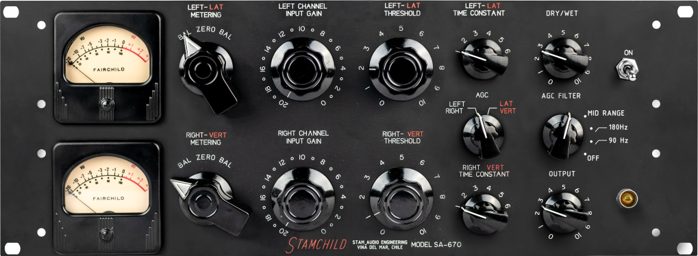
On older models such as the Fairchild 670 (see picture of a clone above), the attack and release times are bundled together through a parameter called “Time Constants”. On a Fairchild for example, the set time constant will have have an attack and release that cannot be adjusted, but are set to complement each other. If you’re on a lower setting, you will have a quicker attack and release time, and a higher setting will give you a slow attack/release time.
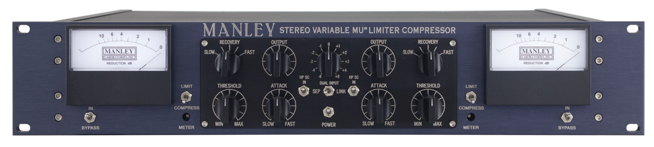
New models like the Manley Variable MU (see picture above) feature not only an attack knob but also a release knob. The attack knob works similar to the attack knob on a 1176 which ranges from slow to fast. The release knob has a different name and is called: ‘recovery’. The recovery knob can be set to different modes going from slow to fast.
COMPRESSORS THAT USE TUBES FOR GR:
Fairchild 670
Altec 436C
Manley Variable MU
SLATE VBC-FG-MU
FET (Field Effect Transistor)
In comparison with an OPTO or VARI-MU, a FET compressor offers (just like a VCA) a very quick transient response, and are solid state by design. The name FET suggests that these compressors use some sort of transistor. A transistor is a semiconductor that can both amplify and attenuate signal based on the settings you dial in. The big difference in the way it’s build, between a VCA compressor and FET compressor sits in the transistors. A VCA compressor has a transistor that is housed with an integrated circuit (an IC) which responds to the voltage of your incoming signal. The FET, however, works with the electrical field as a whole, and gain changes are the result of electrical charges in addition to voltage. In other words; the voltage is applied to the gate. The more voltage you give the lower the resistance in the drain circuit will be. This means that when there’s more voltage –> there’s less resistance –> reduction in gain.
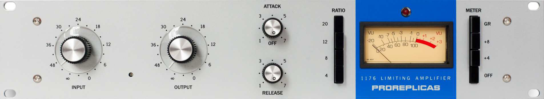
The way this design reduces gain gives it a unique sound. One the most-famous FET compressors is the 1176 (see picture of a clone above). The 1176 is capable of exceedingly fast attack items, but does colour the sound quite a bit. So if you want a fast attack and transparency you’re better off using using a VCA compressor.
What are they used on?
If you want punch, use a FET compressor. It’s a type of compression that has a super fast attack, and therefore works really well on aggressive performances. The slowest attack time on a FET compressor is still faster than a tube compressor. A FET compressor adds a lot of colour to the sound, which can be quite pleasant on drums, vocals, bass, and anything else basically. However, I do tend to not use it on my mixbus because of its colouring. Many engineers use the 1176 for parallel processing because of the aggression and vibe it adds.
Tip 1: You can use both the hardware or software version of the 1176 on a source, but with the compression turned off. The output transformers sound really warm, and will add a bit of a flavour to your sound.
Tip 2: When working with heavier vocal parts such as screams I love to really drive the input level of the FET compressor so that it starts to saturate the vocal in a pleasing way. You can back down the level with output knob so you won’t start clipping
How to use a FET compressor?
The 1176 FET compressor differs from other compressors because it has a fixed-threshold design. This means that if you want more compression you’ll have to dial in the input level. After you’ve dialled in the input level you can use the output knob to determine how much level you’re sending to your tape machine or DAW, this can be used to prevent the source from clipping your DAW converters or the input of your tape machine. The attack and release on a 1176 are marked from 1 - 7. Where on most compressors 1 would be the fastest setting, the 1176 is quite the opposite. On a 1176 compressor is 7 the fastest setting possible and 1 the slowest, this goes for both the attack and release (check the GIF below).
Tip 3: The ‘bread and butter’ setting on a 1176 is setting the attack to be slowest possible and the release the fastest possible. This will ensure that the dynamics are preserved in the recording, tame the loudest transients that come through and quickly go back to zero before you notice compression ever happened.
COMPRESSOR THAT USE FET FOR GR:
1176
1178
mc77
Faking FET 2
Overstayer FET
Aurora Audio GTC2
Pete's place BAC500
Purple Action
Dreamer 1973 / 1978
PWM (Pulse width Modulator)
PWM is an old technology that has been used in vintage compressors but also in modern devices. Using pulse width modulation you’re able to cleanly control the gain-reduction without VCA artifacts. The basic idea is that audio is energy, and in electrical form when you are inside a piece of gear. So if you’re using the compressor to reduce the gain, you’re basically reducing the energy. A VCA compressor lets a percentage of that energy through, determined by a control voltage (it is a variable gain amplifier, or voltage controlled amplifier).
The problem with a VCA compressor is the following: when you change the settings on the compressor, you’re actually changing the control voltage. While doing so it is possible that the control voltage leaks into the audio path which means you’ll hear your compressed signal + dynamically changing distortion. The faster the VCA needs to work, the worse this distortion can become.
So what exactly is PWM? (I’m not sure if I understand this correctly so please correct me if I’m wrong)
Every time we’re changing one of the parameters on our compressor; lets say the threshold, the control voltage changes. Now if we had a switch that would turn off whenever the signal overloads we would get rid of the artifacts. This switch we’re talking about must be able to switch on/off extremely fast. Luckily, the modern PWM gain control circuit design is able to use current technology, and very high speed parts such as that extremely fast switch (we’re talking on/off in less than 1nS). Now in order for the switch to know when it should be turned on and off, a circuit needs to be built that will turn the control voltage into a variable width on-off switching command. This circuit is known as a pulse width modulator. The width of the pulse changes based on the applied control voltage, which basically means whenever you adjust one of the knobs on your compressor, the width of the pulse will change. With a very careful circuit design and a printed circuit layout it is possible to build an accurate system with extremely low artifacts.
What are they used on?
I would personally use a PWM compressor if I don’t want to colour the sound at all. We’ve talked about VCA compressors and we now know that those are pretty clean compressors especially compared to VARI-MU compressors, but a PWM compressor is even cleaner. If you’re into HIFI you’ll love these compressors, but of course just like the other type of compressors they work on many things.
COMPRESSOR THAT USE PWM FOR GR:
Great River PWM-501
Pye Compressor
AC Sound PI-3141
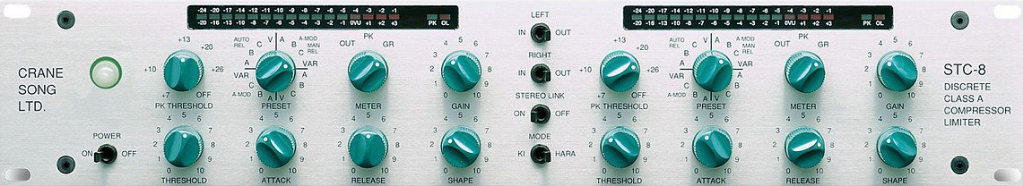
Crane Song STC-8
EMT 156 PDM
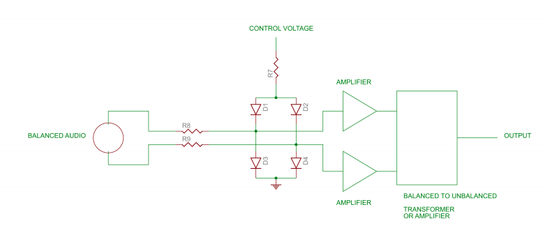
Diode Bridge
What Diode Bridge Compressors separate from other compressors is the distortion that it generates which creates harmonics. Where OPTO and VCA compressors generally do not produce a lot of distortion, diode compressors tend to colour the sound quite a bit.
A diode bridge compressor uses a diode to control the gain reduction. A diode is a non-linear electronic component that conducts the electrical current very well in one direction, but it has a huge amount of distortion. To combat this problem, they dropped the level in front of the diode bridge with 40dB. Doing this brought not only the audio down but also the distortion. After that that diode bridge controlled the gain reduction and this signal was sent to a second transformer which passed the signal to an amplifier chain.
Because this design has quite a high noise floor, people started to use other designs more and more. The diode bridge design still has it’s place though. It adds a certain kind of colour / thickness to a sound like no other design does. Over the years this design has been improved and now has a much lower noise floor. A new design like this can be found in compressors such as the DBC 20 from Buzz Audio.
COMPRESSOR THAT USE DIODE BRIDGE FOR GR:
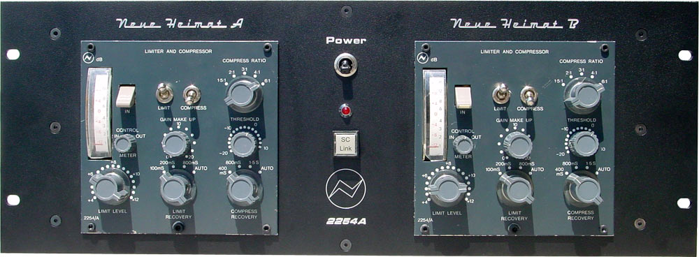
Neve 2254
Neve 33609 (basically the big brother of the 2254)
The Neve 535 (500 series from Neve)
DB54
AMS neve 226
AML 54f50
Buzz Audio DBC 20
Chandler Zener Limiter
Conclusion
It’s hard to fully understand the inner workings off all the different sort of compressors. But unless you’re planning on building your own compressors it’s okay if you don’t exactly know how each compressor was made. I think as engineer/producer it is important to understand what specific designs do to our sound. One compressor may be very slow, but what does this mean for our sound? Or one compressor uses tubes to control the gain reduction and another one uses a controlled voltage, what kind of options do those different compressors give us and once again, what does that mean for our sound?
If we simplify things we could say that there are two different worlds with compressors. In world 1 you want to control the dynamics without changing the sound (e.g. hi-res audio). And in world 2 you want to colour the sound but not use an EQ. The ultimate compressor could do both, but making a hardware unit that is capable of doing so is very hard and expensive. In an ideal world one can put circuits in a box that can do both kinds of sounds, transparent and coloured, but then again we all like different sorts of colours so it rapidly becomes quite complex. In this article we’ve talked about the many different technologies that compressors have been built with over the years. The gain control elements have been; tubes, diodes, optical, PWM, voltage controlled amplifiers, and we discovered that there are several different approaches to them.
A compressor basically consists of 3 parts:
- (1.) The gain control part
- (2.) The control path (sidechain)
- (3.) The audio path
Designing a compressor is a difficult task. Once the gain control part has been sorted out, one needs to deal with the control path. We saw that there are many different compressors with different control paths. An OPTO compressor for example only had one threshold/peak-reduction knob that controlled the gain reduction while a VCA compressor had many different knobs such as the attack, release, ratio, etc. All these different control paths add different sorts of non-dynamic distortion to the signal. The 3rd path (the audio path) even adds more distortion but this time the distortion is dynamic. So when you set the attack time to slow (so that most of the peaks come through) what happens to the peaks? Will they pass through undistorted, or are they going to clip? When they clip, will they hardclip or softclip?
In short: building a compressor is hard but understanding what a specific design does to your sound not so much. By understanding how one design may affect your source we can quickly get the sound we or our client wants 😁. If you scroll back to the top of this post you will find a table that I have made which is basically a quick summary of this entire article.
ps; if I have made any mistakes, or I’m missing something important don’t hesitate to contact me!
Other interesting articles (I will keep updating this list!):
Analog compressors and some of the bits that make them what they are. –> By: Dave Hill
Why a PMW Compressor –> By: Dave Hill
The History of the Neve33609 –> by vintageking
Rupert Neve talking about the development of the Diode Bridge Compressor